Writeup of the Unique challenge
Performing signal analysis on a CAN signal.
Intro
The challenge has a sweet and short intro:
We found a car but we are unable to identify if it's the exact one that we have been searching for. The serial network of the car seems intact so we tapped into it and collected some packets. Can you help us find the VIN of the car that is transmitted repeatedly over the network?
So we are probably going to have to analyse some signals. Time to put my five-year degree in electrical engineering to work!
The Challenge
Extracting the capture results in a file named trace_captured.sal. Now I have never encountered such a file extension, so using the utility file we should get more information about the format itself:
 Results of the
 file utility
…nothing in life is easy, so we resort to googling the file format. It turns out that the file format belongs to a Saleale Logic 2 capture.
Visiting the site of Saleale, it turns out they offer free binaries to capture and analyse a multitude of protocols.
Downloading the binary and opening our trace_captured.sal with it allows for correct parsing of the file:
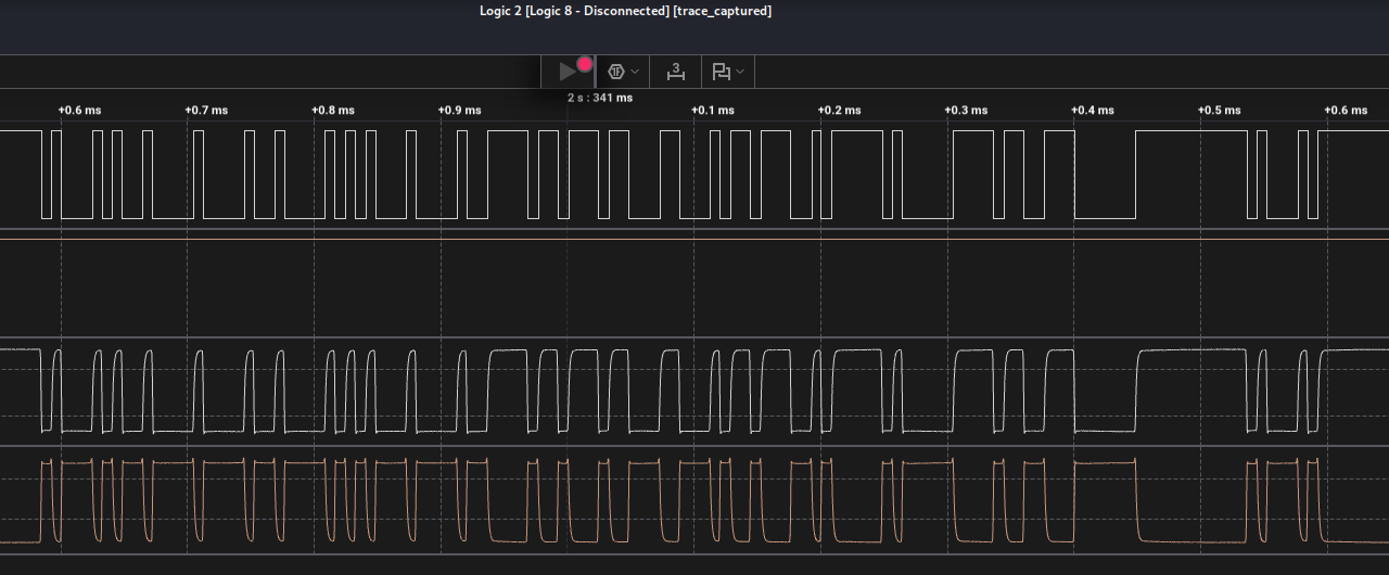 Visual representation of the captured electrical signal
As we are not in the era of cyborgs (at least not yet), we can’t really read the information this signal carries. We know that there’s a bunch of 0’s and 1’s, but to extract the data we need an analyzer.
You can think of an analyzer as a translator that translates the raw electrical signals to a format our human brain can understand. There are a lot of analyzers as there a lot of different protocols (some common ones are SPI, I2C, JTAG, CAN, and etc.)
The challenge intro states that this is a capture of the serial network of a car. Most modern cars rely on the CAN bus protocol, so our analyzer needs to match that.
Luckily Saleale provides a pre-made CAN analyzer:
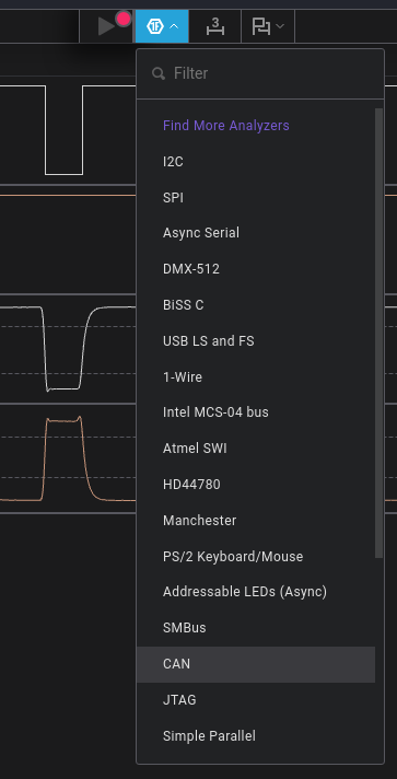 A list of analyzers offered by the binary
The only thing the analyzer requires is the bit rate of the signal:
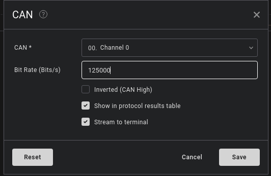 Options of the CAN analyzer
There are two ways to determine the bit rate. The first one is to simply google the standard bit rate of CAN, and you’ll find that it ranges between 125 kbit/s to 500 kbit/s.
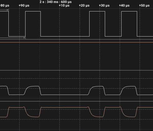
The second way is to calculate it yourself. You see, the CAN bus does not use any modulation, so to calculate the bit rate you only need to find the inverse of the duration of 1 bit.
 Duration of one bit
From the image above, it would seem that the duration of a bit is 7.64 µs. But, we can also see that the length of 2 bits is 16 µs. Due to the imperfection of electrical circuits sometimes the duration of a bit might be longer or shorter than intended. In this case, we can obtain the duration of 1 bit by taking the duration of 2 bits and diving it…by 2. So we get that the duration of a bit is 8 µs.
Taking the reciprocal of that value results in the transfer of 125000 bits per second, or 125 kbit/s.
Using that number as the bit rate allows the analyzer to successfully decode the signal:
 Analyzer displaying the decoded data
To extract the data itself, we can export the data to a csv file and do some command line magic:
cut -d ',' -f 4 data.csv | tr -d '\n\"' | grep -o 'HTB{[^}]*}'
Which results in an output similar to do this:
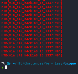 Terminal capture of the above command
You are free to pick the flag, but I think I’ll use: HTB{v1n_c42_h4ck1n9_15_1337!*0^}.
And that’s the challenge.
Extra Mile
As the challenge was pretty straightforward, I wanted to learn a bit more about the CAN bus protocol and the message format it uses.
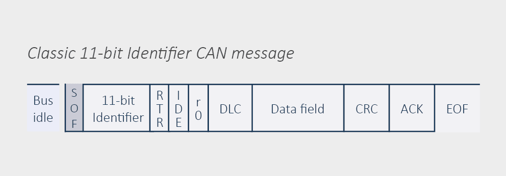 CAN bus message taken from https://www.hms-networks.com/tech-blog/blogpost/hms-blog/2024/06/18/can-message-format-an-overview
Comparing the reference to the signal:
 Forgive my bad writing/drawing…
The signal follows the message structure with the highlighted fields being:
- SOF - Start of Frame field indicating that a new message is coming. Can be seen as the first dip marked with the number 1.
- Following the SOF, the 11-bit identifier is sent together with the RTR (Remote Transmission) flag, IDE (Identifier Extension), and a reserved flag. But if you take a look the entire CAN header should be 14 bits, yet the captured signal states that length is 15 bits?
This is caused by the CAN protocol using bit stuffing, where after five consecutive bits of the same value, a bit is inserted of the opposite value to maintain clock sync. A good example is the data field which should be 8 bits, but in the case a zero is sent the data field is 9 bits long.
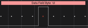 Example of bit stuffing
In addition, this Saleae post says: The red X marks indicate stuffed bits. They are supposed to be there. The X simply lets you know that the bit is not included in the data and is only added for bit stuffing.
With that we can conclude that the 7th bit inside the CAN identifier field (or 8th bit from the start of the CAN message) is an inserted bit.
- The data length field is the next field shown and it’s 4 bits long. In this case the value is 8 (1000 in binary) signaling that 64 bytes of data are expected inside the data field.
- Following the data length field, the first data packet is sent. In this case the data being sent is 11000100 and taking that value and transforming it into hexadecimal yields
\xC4which is also what’s shown by the analyzer.
Skipping over each data field, the end of the message looks like this:
 End of the CAN message
- After the data field, the CRC (Cyclic Redundancy Check) code is sent. This is used to check if data was corrupted during transit. The field itself is 15 bits long.
- In this case, the message is ended with an error field indicating that was an error in the transmission.
And that would be the extra mile challenge done. If you have more knowledge on the CAN protocol, feel free to leave a comment below.
I’ll catch you in the next blog post.